Factors Shaping Extension Precision in Servo-Based CRE Machines

Factors Shaping Extension Precision in Servo-Based CRE Machines

In the ever-evolving landscape of mechanical engineering, Constant Rate of Extension (CRE) machines play a pivotal role in materials testing, research, and development. These machines are designed to apply a controlled, steady extension rate to specimens, allowing for precise analysis of material properties under varying conditions.

At the heart of CRE machines lies a crucial component that dictates their performance and accuracy: the servo motor. The servo motor serves as the powerhouse, driving controlled movements and ensuring the precision demanded by research and industrial applications. As we delve into the intricacies of servo motor-based CRE machines, it becomes evident that achieving optimal extension precision is not a mere luxury but a necessity.

Servo motors, designed for high-precision tasks, facilitate the controlled extension and retraction essential for accurate material testing. Their ability to translate electrical signals into precise mechanical movements makes them indispensable in applications demanding reliable and repeatable results.

The quest for precision in CRE machines is met with a unique set of challenges. Striking the right balance between precision, resolution, and displacement range is paramount. How can we ensure that the servo motor operates seamlessly under diverse conditions while delivering the accuracy required for intricate materials testing?

In this exploration, we will dissect the factors influencing extension precision in servo motor-driven CRE machines. From understanding resolution nuances to considering the impact of displacement range, we aim to unravel the complexities and offer insights into optimizing the performance of these machines. Join us on this journey as we navigate the intricate realm of extension precision and unveil the key considerations for achieving excellence in servo motor-based CRE applications.

The Metrics of Precision: Properties We Aim to Control

In the world of CRE machines, they stretch or compress materials at a steady speed. Throughout this process, they consistently measure and record the force applied to the material at various displacement points. Now, let’s look at the essential characteristics that shape their performance. These properties encapsulate the essence of precision in motion control and materials testing.

  • Displacement Accuracy: The ability of the system to precisely position the specimen in accordance with the intended extension.
  • Displacement Resolution: The smallest increment of movement that the system can detect and act upon
  • Displacement Range (Max. value): The maximum distance over which the CRE machine can extend the specimen
  • Speed Precision: The accuracy with which the machine can maintain a constant extension rate.
  • Speed Range: The range of extension rates or speeds that the CRE machine can achieve.
  • Speed Accuracy: The ability of the system to achieve and maintain the desired extension rate accurately.

Factors Influencing Precision

Let’s look at the factors that wield considerable influence over the key properties we’ve identified. While some factors are within our control, others present fixed parameters that shape the machine’s performance.

  • Gear Ratio: Most of the Servo drives defines Electronic gear ratio which in principal is equivalent to mechanical gear ratio but can be changed easily
  • PPR: Number of external pulse required to complete one full rotation of the servo motor
  • Pitch: The distance between corresponding points on adjacent teeth in a gear or screw.
  • Word Size: The number of bits used to represent a digital word in the control system e.g. PLC

Connecting the Dots

Now that we have seen the properties that we wish to control and the factors which might impact them, let’s try to understand how these are related.

When we use pulse mode control for servo motors, we’re making them move precisely by sending little signals (pulses) from a controller (like a PLC) to the servo drives, which then guides the motor. This controlled movement happens as the motor turns and causes something called a ball screw nut to shift horizontally. The trick is figuring out the exact connection between the number of pulses sent and how much the ball screw nut moves. This connection is uncovered through a step-by-step process called calibration. During calibration, we carefully move a part and keep track of both the pulses sent and the movement. This process helps us understand how to speak the language of servo motor control, giving us the ability to finely control constant rate of extension applications

In simple terms:

               Current Displacement = Np * Pitch / PPR; where

               Np          = Number of external pulse sent for current displacement

               Pitch      = Pitch of the ball-screw

               PPR        = Number of external pulses required for 1 revolution of motor


Looks simple. Right! Well, not exactly. PPR is dependent on a number of factors like electronic gear ratio of the servo drive, mechanical gear ratio between servo motor and ball screw etc. Also, the ball screw pitch may not be precise and contain some error. Due to these reasons, we cannot rely on PPR and pitch to calculate the current displacement of screw nut. Instead, we use an indirect method, called displacement calibration, to accurately compute the current displacement.

Modified formula,

               Current- Displacement = Np * Dc / Npc where;

               Dc           = Displacement used during calibration process

               NPc        = Number of external pulse sent during calibration


Does that mean the displacement calibration is not dependent on other influencing factors like gear ratio and pitch? Well, it is dependent on these factors. The devil lies in the details. Let’s dig a bit deeper.

Let’s try to understand how ‘Np * Dc / Npc’ will be computed. Assuming our controller (a PLC) which is sending these pulses to the servo drive uses 2 words (i.e. 32 bit resisters) to hold ‘Np’, ‘Dc’ and ‘NPc’ values:

               The Max value of ‘Np * Dc’ can be 2,147,483,647 i.e. 2^31

That means, if the product of ‘Np’ and ‘Dc’ is greater than this value, it will lead to an Overflow. Let’s take an example: Say, if PPR is 10,000 and pitch is 5 mm. Just for the sake of understanding, let’s assume no gear is involved and all components are accurate,

1 revolution will displace the screw nut by 5mm.

Let’s say we carried out displacement calibration by moving the nut 500mm with displacement precision of 1 decimal point. If the current displacement is 800 mm then,

               ‘Np * Dc’ => (800/5) * 10,000 * 5,000 => 8,000,000,000 which is > the Max value.

               Result will be an overflow!

 With the current configuration, what will be the max displacement that we can achieve?

Max possible displacement = 2,147,483,647 * 5 / (5,000 * 10,000) = 214.74 mm

That’s pretty low, so how to increase this value? Well, we can do a couple of things:

1) Reduce the displacement during calibration

2) Reduce the PPR or,

Let’s try number #2 first. Let’s say we carried out displacement calibration by moving the nut 50mm with the precision of 1 decimal point. If, like the earlier case, the current displacement is 800 mm then,

               ‘Np * Dc’ => (800/5) * 10,000 * 500 => 800,000,000 which is < the Max value.

               Result will NOT be an overflow!

With the current configuration, what will be the max displacement that we can achieve?

Max possible displacement = 2,147,483,647 * 5 / (500 * 10,000) = 2147.4 mm

But what’s the catch? Let’s see. In manual calibration which is done using a physical scale, there is always some observational error involved. For the sake of calculation, let’s assume that error was 0.25 mm. Let’s calculate again:

               With 0.25 mm error, 50 mm was actually 50.25 mm

               That means, Nc = (10,000 / 5) * 50.25 = 100,500 instead of 100,000

               So, how much error will there be when the actual displacement is 800 mm?

               Error at 800 mm => 3.98 mm


That means, lower the displacement used while calibration, higher may be the displacement error. So, ideally we should calibrate with much bigger value. But as we saw earlier the higher calibration-displacement values may lead to Overflow. Phew! What to do then. Let’s try to manipulate via #2 approach i.e. reduce the PPR instead of calibration-displacement.

We know that the PPR is dependent on gear ratio. Servo drives support electronic gear ratios which can be easily changed. Let’s reduce the PPR to 1000 by increasing the electronic gear ratio 10 times and look at the calculation again. Let’s say we carried out displacement calibration by moving the nut 500mm with the precision of 1 decimal point. If the current displacement is 800 mm then,

               ‘Np * Dc’ => (800/5) * 1000 * 5000 => 800,000,000 which is < the Max value.

               Result will NOT be an overflow!

               Max displacement = 2,147,483,647 * 5 / (5000 * 1000) = 2147.4 mm.

               Error at 800 mm => 0.39 mm

That’s great. Everything sorted! But how much can we reduce the value of PPR? Well we can’t go below a certain value otherwise it will impact the precision and range of the speed. We will cover that in our next blog. Keep watching!

Choosing the right HMI “interface” for your machine!

Choosing the right HMI “interface” for your machine!

Overview

In the world of industrial machines, touch screens have revolutionized the way operators interact with these complex systems. They offer intuitive, user-friendly interfaces that enhance productivity and reduce the learning curve for users. However, selecting the right “interface” between the touch screen and the controller board is a crucial decision that can significantly impact the performance, durability, and reliability of your industrial equipment.

In this blog, we will delve into the essential considerations when choosing the interface for your touch screen in an industrial setting. While there are various factors such as dimensions, resolution, touch-type etc. to take into account when selecting a touch screen, we will specifically focus on the interface between the touch screen and the controller board. This connection is the bridge that facilitates the exchange of information between the operator and the machine, making it a critical element in the overall functionality and longevity of your equipment.

The challenge of choosing the right interface for a touch screen in an industrial machine lies in the multitude of available options. From familiar standards like I2C, SPI and USB to specialized interfaces like DSI, LVDS, eDP, and HDMI, the array of choices can be overwhelming. Each interface has its own strengths and weaknesses, making it essential for industrial equipment designers to navigate this landscape carefully. In the following sections, we will delve into the details of each interface, providing a comprehensive guide to help you make an informed decision based on your specific needs and constraints. Understanding the intricacies of these interfaces is the first step in ensuring the seamless integration of touch screens into your industrial machines, ultimately optimizing their performance and reliability.

Categorization of popular interfaces

There are several ways to categories the popular touchscreen interfaces.

Universal  vs.

  • These are generic interfaces which can be used to transfer any type of data
  • These are low bandwidth or low data rate interfaces
  • Examples: I2C, SPI, USB

Image Transfer

  • These are specially designed for image data transfer
  • Examples: HDMI, DSI, LVDS, eDP

Parallel  vs.

  • Data transfer takes place through several lines
  • Examples: RGB, LVDS

Serial

  • Data transfer takes place through a single line
  • Examples: DSI, I2C, HDMI

Internal  vs.

  • Display and controller components usually share the same enclosure
  • Examples:  RGB, DSI, LVDS, Vx1

External

  • Here two separate devices are connected by an external cable
  • Examples: HDMI, DP, VGA

Deep Dive

Let’s deep dive into some of the popularly used touch screen interfaces and try to understand their pros and cons.

HDMI

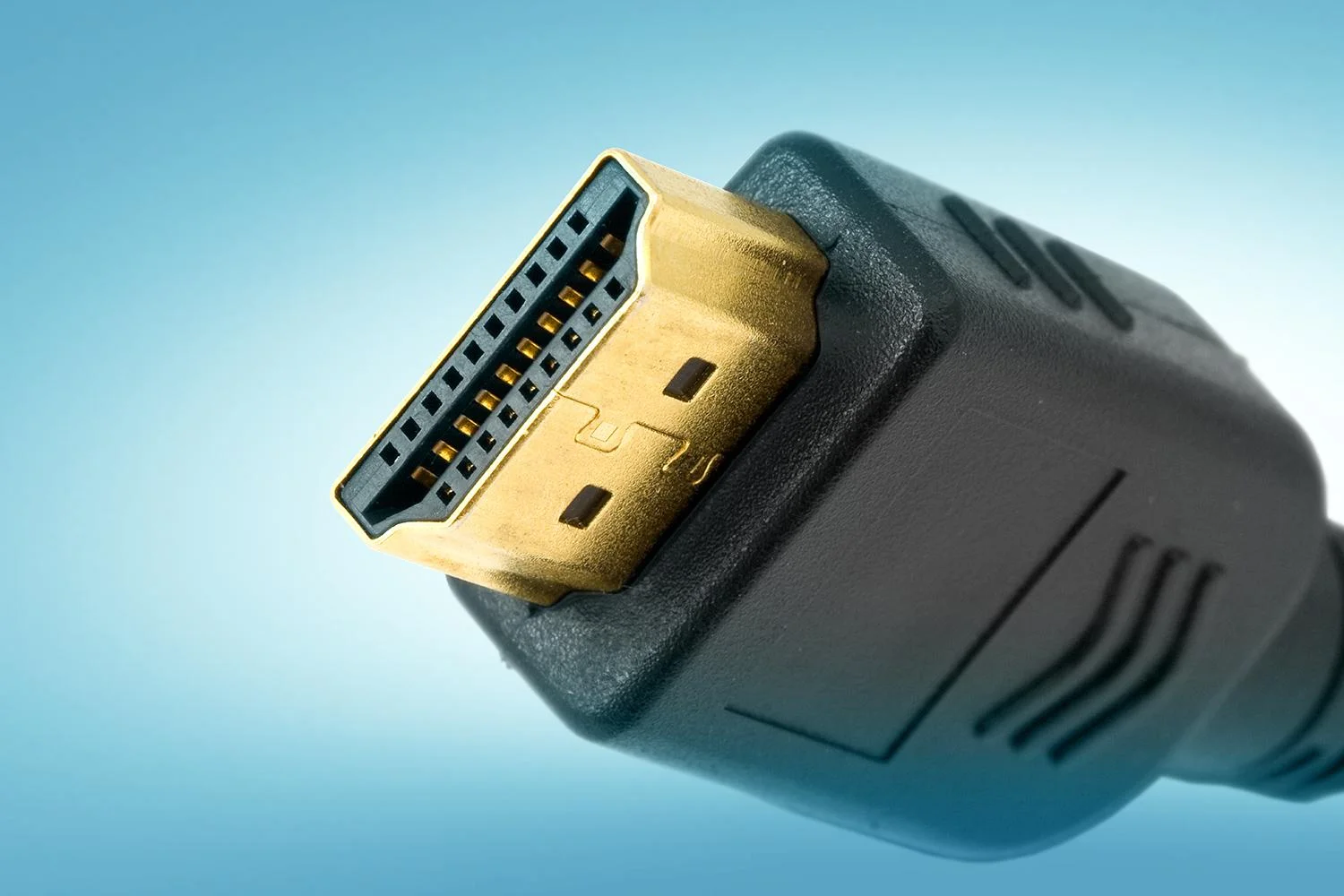
HDMI (High Definition Multimedia Interface) is a widely used interface for transmitting audio and video signals between devices. It falls under following categories: Serial, Image transfer and External

HDMI Image

Pros

  • Widespread Compatibility: HDMI is a widely supported standard, making it easy to find displays and touch screens that work with the a single board computer (SBC)
  • High-Quality Video: HDMI provides high-quality video output, making it suitable for multimedia applications
  • Audio Support: HDMI can carry audio signals as well
  • High Refresh rate, multiple resolution support and multiple devices support

Cons

  • Limited Touchscreen Support: HDMI alone doesn’t provide native touchscreen support. You may need to use a separate USB interface for the touchscreen, which can be less integrated
  • Somewhat costly

DSI

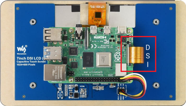
DSI (Display Serial Interface) is a high-speed serial interface commonly employed in mobile devices for connecting displays and touch screens. It has been developed and maintained by MIPI (Mobile Industry Processor Interface). Its serial nature facilitates fast data transmission while maintaining power efficiency. It falls under following categories: Serial, Image transfer and External

HDMI Image

Pros

    • Integrated Touchscreen Support: DSI supports both video and touchscreen input in an integrated manner
    • Power Efficiency: DSI is designed for mobile and embedded devices and is power-efficient
    • Optimized for SBC like Raspberry Pi: DSI is the native interface for the official Raspberry Pi touchscreen displays, ensuring compatibility and good performance
    • Moderate price and high refresh rate

    Cons

    • Limited Display Options: DSI displays are somewhat limited in terms of options and availability compared to HDMI displays

    LVDS

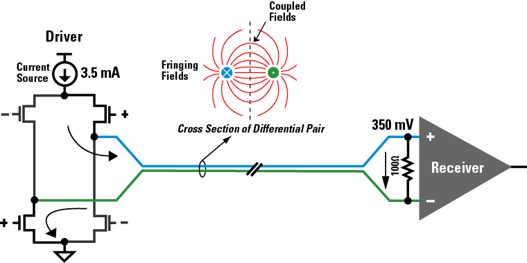
    LVDS (Low Voltage Differential Signal) is a parallel interface that has found widespread use in touch screen technology, contributing to the development of responsive and high-performance touch-enabled devices. Touch screens utilizing LVDS benefit from its capacity to handle large amounts of data efficiently. LVDS is commonly used in industrial settings and can be suitable for specific use cases. It falls under the following categories: Parallel, Image transfer and Internal

    HDMI Image

    Pros

      • High-Speed Data Transfer: LVDS is designed for high-speed data transmission, making it suitable for touch screen interfaces that require quick response times and smooth interactions
      • Low Power Consumption: LVDS is known for its low power requirements, contributing to energy-efficient touch screen devices. This is especially crucial for portable devices with limited battery life
      • Reliable and Robust: LVDS is known for its noise immunity and robust signal transmission

      Cons

      • Less Common in Consumer Displays: LVDS displays are less common in consumer markets, so finding compatible displays might be more challenging
      • Configuration Complexity: Configuring LVDS displays may require more effort and configuration than plug-and-play options like HDMI or DSI
      • Higher cost and compatibility challenges

      eDP

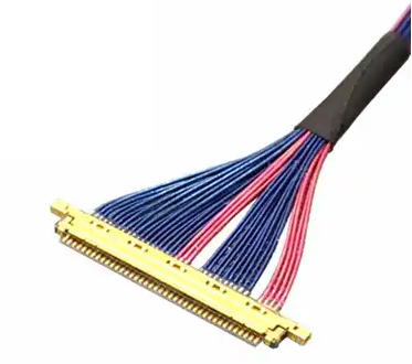
      eDP (Embedded Display Port) is a high-speed serial interface primarily used to connect display devices, including touch screens, to various computing platforms. Its compact form factor and high data transfer rates make it ideal for portable devices. It’s a powerful interface with numerous advantages, especially in high-performance touch screen devices. However, its complexity, cost, and considerations regarding cable length should be carefully weighed against the specific requirements of the application. It falls under the following categories: Serial, Image transfer and External

      HDMI Image

      Pros

        • High Performance: eDP is capable of providing high-resolution and high-refresh-rate displays
        • Native Support for Some Displays: Some small form-factor displays use eDP as their primary interface

        Cons

        • Less Common: eDP displays may be less common and, therefore, more challenging to find compared to HDMI or DSI displays
        • May Require Adapters: Some eDP displays may require adapters to connect to the SBC like Raspberry Pi

        I2C

        I2C (Inter Integrated Circuit) is a two-wire, bidirectional communication protocol suitable for connecting multiple devices on the same bus. Touch screen interfaces utilizing I2C benefit from its simplicity and the ability to address multiple devices on a single connection. It falls under the following categories: Serial, Universal and Internal

        HDMI Image

        Pros

          • Simplicity and Low Pin Count: I2C uses a two-wire communication protocol, which simplifies the wiring and reduces the pin count compared to some parallel interfaces. This simplicity can make it easier to implement and troubleshoot
          • Addressing Multiple Devices: I2C supports multiple devices on the same bus, each with a unique address. This allows touch screens and other peripherals to share the same communication lines, reducing the number of wires needed in the system
          • Standardized Protocol: I2C is a standardized protocol, ensuring compatibility between devices from different manufacturers. This standardization facilitates interoperability and simplifies the integration of touch screen interfaces into larger systems
          • Low Power Consumption and low cost

          Cons

          • Limited Data Transfer Speed: I2C may have slower data transfer rates compared to some other serial interfaces, which could impact the responsiveness of touch screens in high-performance applications
          • Not Ideal for High-Bandwidth Applications: I2C may not be the best choice for touch screens with high data bandwidth requirements, such as those with large displays or high-resolution graphics
          • Low refresh rate and resolution

          RGB

          RGB (Red Green Blue) is a standard colour model used in displays, and RGB interfaces facilitate parallel transmission of video data. Touch screens employing RGB interfaces benefit from the simultaneous transfer of colour information, ensuring vibrant visuals. It falls under the following categories: Parallel, Image transfer and Internal.

          HDMI Image

          Pros

            • High Image Quality: RGB interfaces are known for delivering high image quality, making them suitable for applications where colour accuracy and vibrancy are critical
            • Parallel Data Transmission: RGB interfaces use parallel data transmission, allowing for the simultaneous transfer of multiple bits of data. This parallelism contributes to higher bandwidth and faster data transfer rates, which is beneficial for applications with high-resolution displays (bandwidth estimated at up to 1.2 GB/s)
            • Widespread Compatibility: RGB is a standard colour model widely used in display technologies. The prevalence of RGB interfaces ensures compatibility with a broad range of devices, making it easier to integrate touch screens into various systems.
            • Cost-Effective

            Cons

            • Higher Power Consumption: Parallel interfaces like RGB may consume more power compared to certain serial interfaces. While this might not be a significant concern in some applications, it can impact the overall power efficiency of the device, especially in portable or battery-powered scenarios
            • Bulkier Design: Due to the higher number of wires and the parallel nature of the interface, devices utilizing RGB may have bulkier designs compared to those using more streamlined serial interfaces
            • Potential Electromagnetic Interference: The presence of multiple parallel lines in RGB interfaces may increase the susceptibility to electromagnetic interference. Shielding and careful design considerations are necessary to minimize the impact of interference on touch screen performance

            Wrap Up

            We hope this exploration of touch screen interfaces has been insightful. Whether you’re navigating the complexities of LVDS, embracing the simplicity of I2C and SPI, or enjoying the visual richness of RGB, each interface plays a crucial role in enhancing human-device interactions. For further details, consulting, or any inquiries, feel free to get in touch with us. Your journey into the world of touch screen technology continues, and we’re here to assist every step of the way.

            Benefits of Non-exclusive software license for Small Manufactures

            Creating a world-class machine requires careful consideration of multiple factors, and high-quality software is undoubtedly one of them. However, small manufacturers, especially SMEs, often face challenges in acquiring such software due to limited funds, resources, and in-house expertise. Building an internal team or outsourcing software development can be expensive options for them. This blog highlights the benefits of a third approach – the non-exclusive software license model, where the partner software organization retains the intellectual property rights. This model offers a win-win situation, enabling small manufacturers to access top-notch software solutions while minimizing costs and leveraging the expertise of software providers.

            The non-exclusive software license model can indeed be beneficial for small manufacturers for a number of reasons:

            1) Cost-Effective: Small manufacturers often have limited financial and human resources to invest in digitalization initiatives. Acquiring the necessary technology, expertise, and infrastructure can be a significant hurdle. Non-exclusive licenses allow small manufacturers to access and use software at a lower cost compared to exclusive licenses. This is particularly advantageous for small businesses with limited budgets, as they can leverage the required software without significant upfront investments.

            2) Reduced Maintenance and Support Burden: Non-exclusive licenses often come with maintenance and support services provided by the software vendors. This relieves small manufacturers from the burden of managing and maintaining the software themselves, allowing them to focus on their core business activities.

            3) Innovation and Adaptability: Non-exclusive licenses encourage innovation and experimentation within small manufacturing businesses. They can explore and adopt new software solutions or technologies that align with their specific needs and goals, fostering adaptability and staying up-to-date with industry advancements.

            4) Collaboration and Compatibility: Non-exclusive licenses promote collaboration and compatibility among different software systems. Small manufacturers can integrate multiple software applications from various vendors to streamline their operations, improve data sharing, and optimize workflows.

            Overall, the non-exclusive software license model offers small manufacturers affordability, flexibility, scalability, access to diverse solutions, and the opportunity to innovate and collaborate effectively. It allows them to leverage software tools and technologies to optimize their operations, improve productivity, and gain a competitive edge in the market.

            Part – 3: Strategies for SMEs to Overcome Challenges in Adopting Industry 4.0 Technology for Products

            Part – 3: Strategies for SMEs to Overcome Challenges in Adopting Industry 4.0 Technology for Products

            In Part-1 of this three part series, we saw that Industry 4.0 offers several key benefits, including increased productivity, improved efficiency, enhanced automation, optimized supply chains, better decision-making through data analytics, cost savings through predictive maintenance, customization and personalization of products, and improved safety and sustainability in manufacturing processes. In Part-2, we discussed the challenges associated with adoption of this technology for small OEMs (Original Equipment Manufacturers).

            In this final part, let’s discuss the strategies which can be implemented by small manufacturers to overcome the challenges:

            1) Develop a Clear Digitalization Strategy: Create a comprehensive roadmap outlining the goals, objectives, and desired outcomes of the digitalization process. Align the strategy with the overall business objectives and prioritize initiatives based on their potential impact.
            2) Seek Expert Guidance: Engage with industry experts, consultants, or technology partners who specialize in digital transformation. Their expertise and experience can provide valuable insights, guidance, and support in implementing the right technologies and overcoming technical challenges.
            3) Build a Digital Culture: Foster a culture of innovation and continuous learning within the organization. Encourage employees to embrace digital technologies and provide training programs to enhance their digital literacy. Effective change management is crucial to ensure smooth adoption and acceptance of new digital processes.
            4) Start with Small Steps: Begin the digitalization journey with manageable pilot projects or smaller initiatives. This approach allows for testing and fine-tuning of technologies, identifying potential challenges, and showcasing tangible benefits to gain support and momentum for broader implementation.
            5) Collaborate and Network: Engage with industry associations, trade groups, or local business networks to collaborate and share knowledge with peers facing similar challenges. Collaborative initiatives can provide access to shared resources, best practices, and collective problem-solving.
            6) Secure Funding: Explore funding opportunities available through government grants, subsidies, or industry-specific programs to support digital transformation initiatives. These financial resources can help alleviate the financial burden associated with investing in technology and infrastructure upgrades.
            7) Address Data Security and Privacy: Implement robust cybersecurity measures to protect sensitive data and ensure compliance with privacy regulations. Prioritize data security and educate employees about best practices to mitigate potential risks.
            8) Foster Partnerships: Form strategic partnerships with technology providers, suppliers, or customers to leverage their expertise and resources. Collaborative partnerships can help overcome resource limitations and facilitate access to necessary technologies or markets.
            9) Monitor Industry Trends: Stay informed about emerging technologies, industry trends, and best practices in digital transformation. Regularly assess and adjust the digitalization strategy to remain agile and competitive in a rapidly evolving landscape.
            10) Measure and Evaluate Progress: Define key performance indicators (KPIs) to track the progress and success of digital transformation initiatives. Regularly evaluate the impact of digitalization efforts, identify areas for improvement, and make necessary adjustments to the strategy.

            By adopting a systematic and proactive approach, small manufacturers can overcome challenges and successfully navigate their digital transformation journey, unlocking the benefits of increased efficiency, competitiveness, and growth in the digital era.

            Part – 2: Navigating the Digitalization Path: Challenges Faced by Small Manufacturers on the Road to Transformation

            As we saw in Part-1 of our three part series on Industry 4.0, it offers several key benefits, including increased productivity, improved efficiency, enhanced automation, optimized supply chains, better decision-making through data analytics, cost savings through predictive maintenance, customization and personalization of products, and improved safety and sustainability in manufacturing processes. Like any other technology, the adoption of Industry 4.0 poses some challenges.

            We all know that Small and Medium-sized Enterprises (SMEs) are the driving force of many manufacturing economies. As the backbone of the manufacturing industry, SMEs’ impact on the Fourth Industrial Revolution is significant. But they often face different challenges and barriers than larger companies.

            Following are some of the key challenges faced by SMEs for adopting Industry 4.0 in their products:

            1) Limited Resources: Small manufacturers often have limited financial and human resources to invest in digitalization initiatives. Acquiring the necessary technology, expertise, and infrastructure can be a significant hurdle.
            2) Lack of Technical Expertise: Implementing digital technologies requires specialized knowledge and skills. Small manufacturers may struggle to find or afford experts who can guide them through the digital transformation process.
            3) Legacy Systems and Infrastructure: Many small manufacturers still rely on outdated or legacy systems and equipment. Integrating new technologies with existing infrastructure can be complex and costly.
            4) Data Management and Security: Digitalization generates vast amounts of data, and small manufacturers may face challenges in effectively managing and analyzing this data. Ensuring data security and protecting sensitive information can be particularly daunting for companies with limited cybersecurity resources.
            5) Change Management: Transitioning to a digitalized environment involves cultural and organizational changes. Resistance to change, employee training, and managing the transition process can pose challenges for small manufacturers.
            6) Scalability and Adaptability: Small manufacturers often face the challenge of scaling up their digital capabilities to meet growing demands or adapt to changing market trends. Ensuring that digital systems and processes can be easily scaled and adapted is crucial for long-term success.
            7) Return on Investment (ROI): Small manufacturers need to carefully evaluate the potential return on investment for digitalization initiatives. Balancing the upfront costs with the expected benefits and calculating the ROI can be challenging, especially when the results may not be immediate.
            8) Connectivity and Infrastructure: Connectivity issues, such as limited internet access or unreliable networks, can hinder the implementation of digital technologies. Small manufacturers may need to address infrastructure challenges to fully leverage the benefits of digitalization.
            9) Market Competition: Keeping up with larger competitors who have already embraced digitalization can be a significant challenge for small manufacturers. They must find unique value propositions, niche markets, or innovative approaches to differentiate themselves.

            Overcoming these challenges requires strategic planning, prioritization, and seeking support from industry experts, government initiatives, or business networks. Collaborating with technology partners, investing in employee training, and adopting a phased approach to digital transformation can help small manufacturers navigate these obstacles and unlock the benefits of digitalization. We will discuss the strategies which can be used to overcome these challenges in Part -3 of our three part series.

            Part – 1: Unlocking Growth Potential: How Industry 4.0 Empowers SMEs in Manufacturing Products

            In this three-part series, we explore the advantages of manufacturing the products empowered by Industry 4.0 specifically from the perspective of SMEs (Small and Medium Enterprises). We will also look at their unique challenges and discuss the strategies to overcome those challenges.

            Industry 4.0

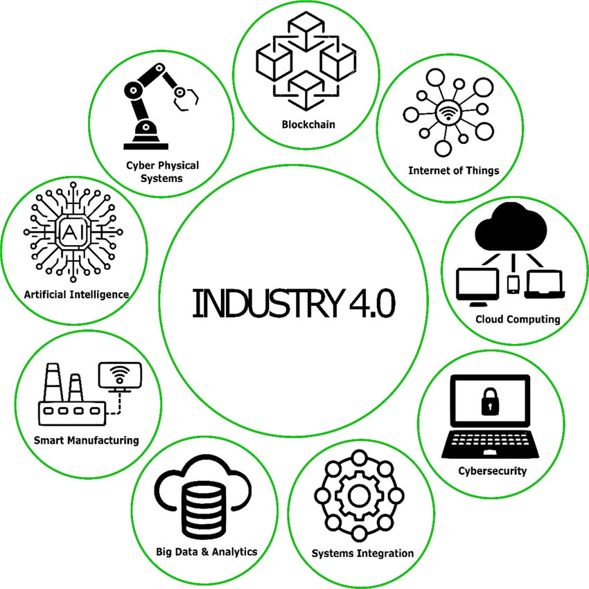
            The 4th revolution in manufacturing, also known as Industry 4.0, represents the convergence of 8advanced technologies and digital transformation in the manufacturing sector. It involves the integration of cyber-physical systems, IoT, cloud computing, big data analytics, and artificial intelligence to create smart and interconnected manufacturing environments. As we can see, Industry 4.0 encompasses various technical terms, but let’s focus on understanding the benefits rather than delving deep into the specific technologies involved specifically from small OEMs perspective.

            Small original equipment manufacturers (OEMs) can benefit from producing IoT-based products for several reasons:
            1) Market Demand: The IoT market is growing rapidly, and there is a rising demand for connected devices and smart solutions across various industries. By producing IoT-based products, small OEMs can tap into this expanding market and meet the needs of customers who are seeking innovative and connected solutions.
            2) Competitive Advantage: Offering IoT-based products allows small OEMs to differentiate themselves from competitors. By integrating IoT capabilities into their products, they can provide additional value to customers, such as remote monitoring, automation, data analytics, and enhanced functionality. This can give them a competitive edge in the marketplace.
            3) Improved Customer Experience: IoT-enabled products can enhance the overall customer experience. By connecting devices, collecting data, and enabling remote control or monitoring, small OEMs can provide convenience, personalized experiences, and proactive maintenance and support services to their customers. This can result in higher customer satisfaction and loyalty.
            4) Operational Efficiency: IoT technologies offer opportunities for small OEMs to optimize their own operations. By implementing IoT solutions within their manufacturing processes, supply chains, and inventory management systems, they can improve efficiency, reduce costs, minimize downtime, and enhance productivity.
            5) Business Insights: IoT devices generate vast amounts of data, which, when properly analyzed, can provide valuable insights into customer behavior, product performance, and market trends. Small OEMs can leverage this data to make data-driven decisions, improve their products and services, and identify new business opportunities.
            6) Long-Term Revenue Streams: IoT-based products can create long-term revenue streams for small OEMs. By offering connected devices, they can establish ongoing relationships with customers through software updates, subscription models, and additional value-added services. This can provide a recurring revenue stream beyond the initial product sale.

            Like any other technology, the adoption of Industry 4.0 poses some challenges for SMEs (Small and Medium Enterprises). It’s important for small OEMs to carefully consider their resources, capabilities, and target market when deciding to produce IoT-based products. Proper planning, understanding customer needs, ensuring data security and privacy, and investing in the right talent and infrastructure are crucial for success in the IoT space. We will cover them in detail in Part-2 of this three part series.